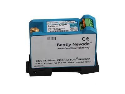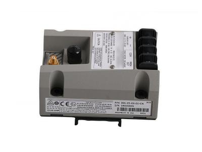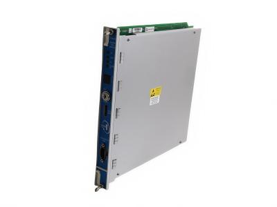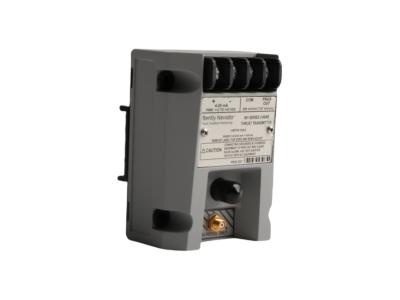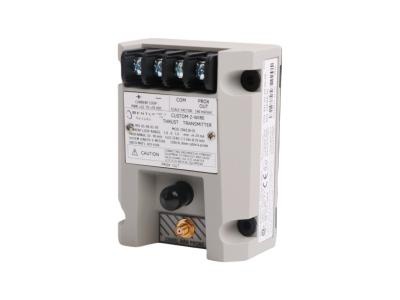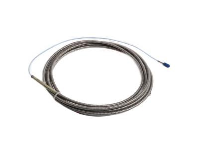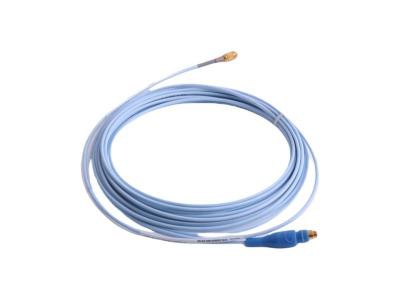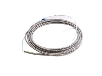
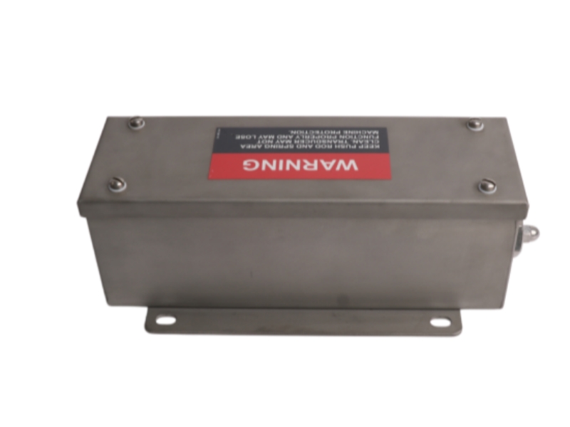
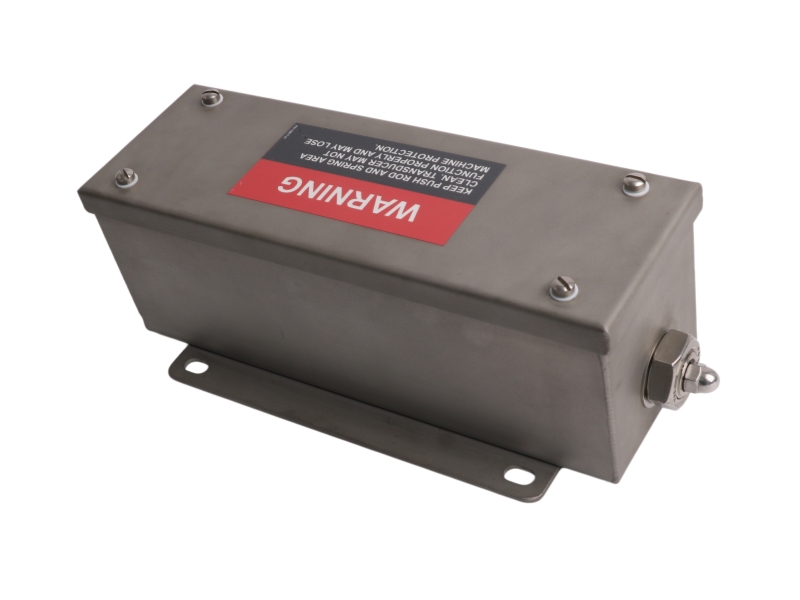
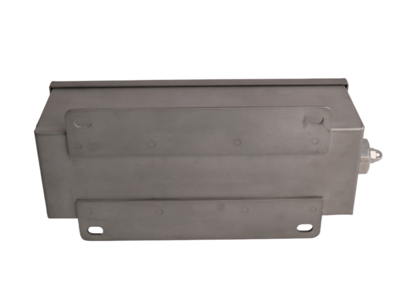
The 24765-02-01 is a Bently Nevada DC-LVDT case expansion transducer system featuring a ±25.4 mm (±1.00 in) linear displacement range with a highly responsive mechanical spring return mechanism. Fully compatible with 3300 or 3500 series position monitors, this unit works seamlessly inside a weatherproof NEMA 3 enclosure to deliver precise thermal growth tracking and sliding foot obstruction detection for large industrial turbines.
Specifications
- Input Power: +24 V DC, minimum 30 mA
- Scale Factor: 0.404 V/mm (10.25 V/in)
- Linear Range: ±25.4 mm (±1.0 in)
- Frequency Response (-3 dB): 15 Hz
- Output Impedance: 7 kΩ nominal
- Minimum Load Resistance: 100 kΩ
- Output Characteristics: <1% ripple, ±0.5% linearity, 0.125% stability
- Temperature Coefficient: 0.07%/°C
- Operating Temperature: -18°C to +71°C
- Storage Temperature: -54°C to +93°C
Application
-
Turbine Case Expansion Monitoring
Used in TSI systems to measure thermal growth of turbine casings during startup and operation. -
Power Generation Equipment Protection
Applied in steam and gas turbines to ensure safe thermal alignment and stable operation. -
Rotor-to-Stator Contact Prevention
Detects uneven thermal growth to prevent rubbing between rotating and stationary components. -
Mechanical Fault Detection
Identifies issues such as jammed or obstructed sliding feet on turbine casings for early maintenance action.
Ordering Information Table Breakdown
This table decodes the implicit mechanical and functional configuration designated by the part number 24765-02-01:
|
Option Code |
Parameter |
Configured Value & Technical Meaning |
|
24765 |
Base Model |
Case Expansion Transducer Assembly (dc LVDT, NEMA 3 Enclosure) |
|
02 |
A: Linear Range Option |
±25.4 mm (±1.00 in) total stroke / 50.8 mm (2.0 in) total linear range |
|
01 |
B: Spring Option |
Housed configuration including internal integrated spring return |
Installation & Troubleshooting FAQ
Q1: What are the exact power supply parameters and electrical scale output values for this LVDT model?
A: The 24765-02-01 requires a continuous input supply voltage of +24 Vdc with a minimum operational current draw of 30 mA. For field calibration and validation procedures, the sensor delivers a linear output scale factor of exactly 0.404 V/mm (10.25 V/in) over its total stroke path.
Q2: What is the significance of the signal frequency response curve, and does longer field wiring impact its stability?
A: The 24765-02 assembly maintains a defined -3 dB frequency attenuation cutoff point at 15 Hz with a typical output signal ripple factor under 1% of the full-scale span. For long-distance sensor deployments up to 305 meters (1,000 feet), users must utilize an isolated 3-conductor shielded triad field cable to suppress high-frequency signal roll-off and environmental electrical interference.
Q3: Why is a dual-transducer installation setup mandatory for tracking standard case expansion metrics?
A: Machine casing units are designed to slide uniformly on mounting surfaces as thermal parameters shift. If one sliding foot becomes obstructed, jammed, or bound by friction, the casing will distort asymmetrical vectors, leading to internal component binding. A dual-transducer arrangement tracks each side independently to sound critical differential alignment alarms before heavy structural destruction occurs.
Accessories
| 135941-01 | 127 mm (5.0 in) rod |
| 135941-02 | 152.4 mm (6.0 in) rod |
| 135941-03 | 228.6 mm (9.0 in) rod |
| 135941-04 | 304.8 mm (12.0 in) rod |
| 285741 | Ferrite Bead |





 For the quick assistance message us on WhatsApp at