Product-specific procurement page for verified identification, compatibility review and replacement planning.
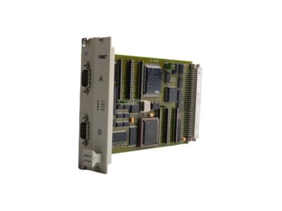
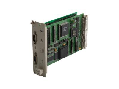
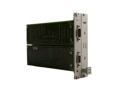
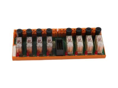
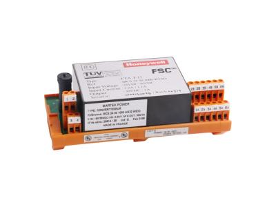
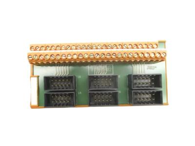
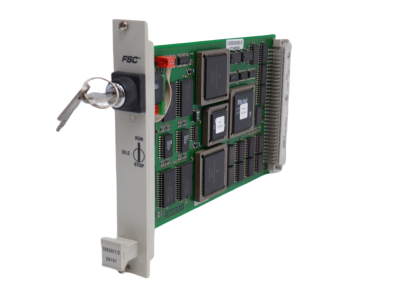
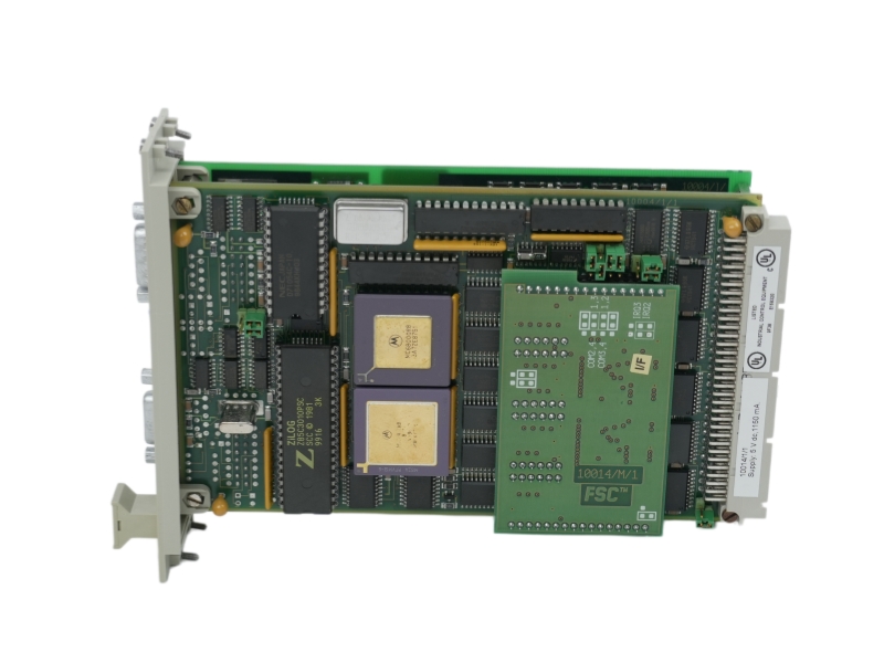
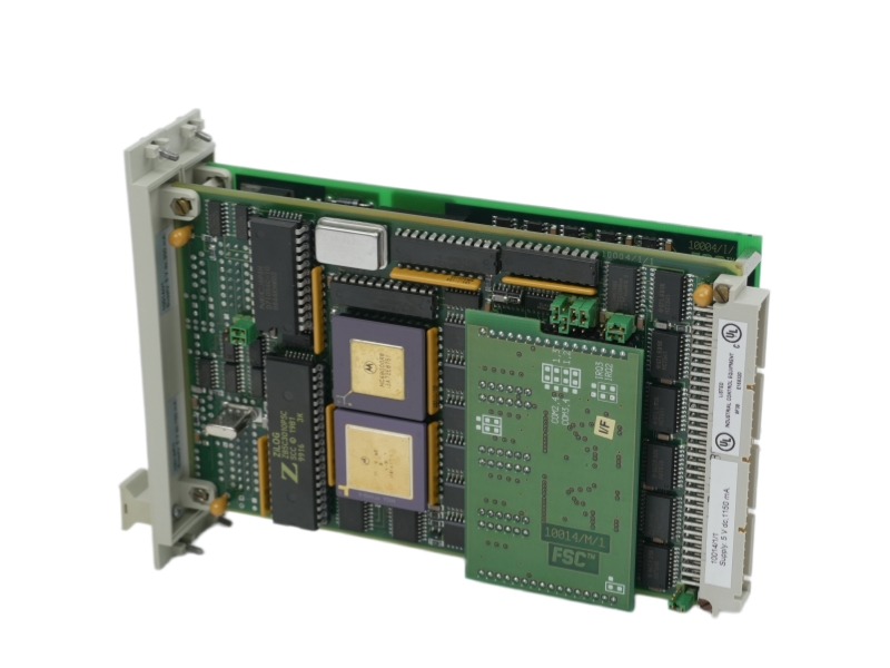
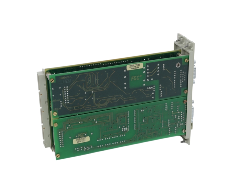
The Honeywell 10014/I/F is a fail safe control isolated communication interface module used in industrial automation or machinery monitoring service work. This page focuses on the exact identifier and the checks needed before replacement. It is intended for maintenance teams, system integrators and buyers handling installed equipment. Confirm the complete nameplate, mechanical configuration, electrical interface, associated system components, hardware revision, firmware or software version and destination requirements before ordering. Product condition, availability and written warranty terms must be confirmed for the specific offered unit.
| Manufacturer | Honeywell |
|---|---|
| Complete Part Number | 10014/I/F |
| Product Type | Fail Safe Control Isolated Communication Interface Module |
| Series | Contact us to confirm. |
| Product Condition | Contact us to confirm. |
| Hardware Revision | Contact us to confirm. |
| Firmware/Software Version | Contact us to confirm. |
| Country of Origin | Contact us to confirm. |
| Compatibility | Confirm the installed system, complete suffix and label information. |
| Warranty | Contact us for written quotation terms. |
| Availability | Contact us to confirm. |
| Shipping | Worldwide shipping options are checked with each quotation. |
Isolated communication interface module associated with Honeywell Fail Safe Control systems
Exact interface, firmware and system release compatibility require confirmation from the installed module label and project documentation
Use only after matching the complete identifier 10014/I/F
Verify the complete model and suffix, system total length, voltage and interface, hardware version, firmware or software version, mounting dimensions, target material where applicable, and original equipment label photos. Do not treat a related family member as a direct substitute.
Availability changes and must be checked when a quotation is requested.
Send the complete label, installed system information and relevant mechanical or electrical details for review.
Yes. Every suffix and modification identifier can affect configuration and must be verified.
Request current photos for the specific offered item before ordering.
Worldwide shipping options are checked after the destination and order requirements are confirmed.
Send us the complete part number, required quantity, destination country and product label photos. Our team will check availability, condition, compatibility requirements and shipping options.
Verification, documentation, packaging and international logistics support for the exact offered item.
Details are checked for the confirmed quotation and order.
Details are checked for the confirmed quotation and order.
Details are checked for the confirmed quotation and order.
Details are checked for the confirmed quotation and order.
Details are checked for the confirmed quotation and order.
Details are checked for the confirmed quotation and order.
Details are checked for the confirmed quotation and order.
Details are checked for the confirmed quotation and order.
Details are checked for the confirmed quotation and order.
Stockoems is operated by Apter Power Limited and is an independent reseller of industrial automation products. Manufacturer names and trademarks are used for identification purposes only.
No unconfirmed stock or lead time is promised.
Independent product listings for broader maintenance and procurement planning.
Each entry is an independent product listing and is not presented as a direct replacement. Confirm the manufacturer, complete part number, revision and compatibility before ordering.
| Vibro-Meter MPC4 |
Vibro-Meter IOC4T |
Vibro-Meter AMC8 |
Vibro-Meter IOC8T |
Vibro-Meter CPUM |
| Vibro-Meter IOCN |
Vibro-Meter CPUR |
Vibro-Meter IOCR |
Vibro-Meter RLC16 |
Vibro-Meter IRC4 |
| Bently Nevada 330103-04-13-10-02-00 |
Honeywell 51305482-205 |
Emerson KC4011X1-BD1 12P6758X022 |
Bently Nevada 330103-05-12-10-01-00 |
Honeywell 51305482-210 |
| Emerson KJ1501X1-BC1 12P2186X032 VE5008 |
Bently Nevada 330103-05-15-05-02-00 |
Honeywell 51305482-220 |
Emerson KJ2002X1-CA1 12P1509X102 VE3004 |
Bently Nevada 330130-070-00-00 |
| Honeywell 51305482-250 |
Emerson KJ2201X1-BA1 12P3162X182 SLS1508 |
Bently Nevada 330130-070-00-05 |
Honeywell 51305786-502 |
Emerson KJ2201X1-JA1 12P3323X042 |
| Bently Nevada 330130-075-00-CN |
Honeywell 51305980-124 |
Emerson KJ3001X1-BG1 12P0557X162 |
Bently Nevada 330130-085-02-00 |
Honeywell 51305980-184 |
| Emerson KJ3001X1-BJ1 12P0555X152 |
Bently Nevada 330130-085-03-00 |
Honeywell 51305980-224 |
Emerson KJ3002X1-BA1 12P0680X122 |
Bently Nevada 330180-X1-CN MOD:143416-29 |
| Honeywell 51305980-284 |
Emerson KJ3002X1-BC1 12P0681X092 |
Bently Nevada 330180-X1-CN MOD:145004-141 |
Honeywell 51403578-100 |
Emerson KJ3007X1-EA1 12P2413X032 |
| Siemens 6ES5948-3UR23 |
Siemens 6SL3224-0BE31-1UA0 |
Siemens 6GK1143-0TB01 |
FANUC A06B-6096-H106 |
FANUC A06B-6096-H104 |
| FANUC A06B-6087-H155 |
ABB BC810K02 3BSE031155R1 |
Honeywell 10014/I/F |
Bently Nevada 330171-00-14-10-02-05 |
Bently Nevada 146054-14-10-02-00 |
| Bently Nevada 143493-00-080-080-70-00 |
Bently Nevada 21501-00-16-05-02 |
Bently Nevada 330901-05-55-05-11-05 |
GE HE693ADC415 |
MCGS TPC1061Ti |
| Allen-Bradley 1756-L71 |
Allen-Bradley 1756-EN2T |
ABB PM866K01 3BSE050198R1 |
Emerson KJ3002X1-BF1 12P1732X012 |
Honeywell CC-PAIH01 51405038-175 |
| Yokogawa AAI141-S00 |
Yokogawa ADV151-P00 |
HIMA F8650X |
Triconex 3008 |
Triconex 3700A |
| Foxboro FBM201 |
Foxboro FBM204 |
Siemens 6ES7134-4GB11-0AB0 |
ABB CI854AK01 3BSE030220R1 |
Emerson VE4003S2B1 |
Send the required model, quantity, destination country and label photos for availability and compatibility checks.