1770-CD Product datasheet
|
Model number: |
1770-CD |
|
Module Type: |
Twinaxial Cable |
|
Manufacture: |
Allen-Bradley |
|
Condition: |
Brand New |
|
Range of Product: |
Allen-Bradley |
|
Lead time: |
In Stock |
|
Weight: |
0.9kg |
|
HS CODE: |
8537101190 |
|
Dimension: |
3.5x13x14.5cm |
|
MOQ: |
1 |
|
Product Origin: |
USA |
|
System: |
PLC |
|
Discontinued on: |
Jane 30,2016 |
|
Communication Service: |
Ethernet router |
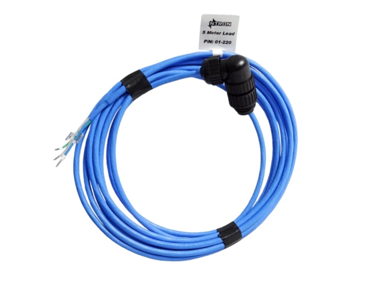
1770-CD Functional Description
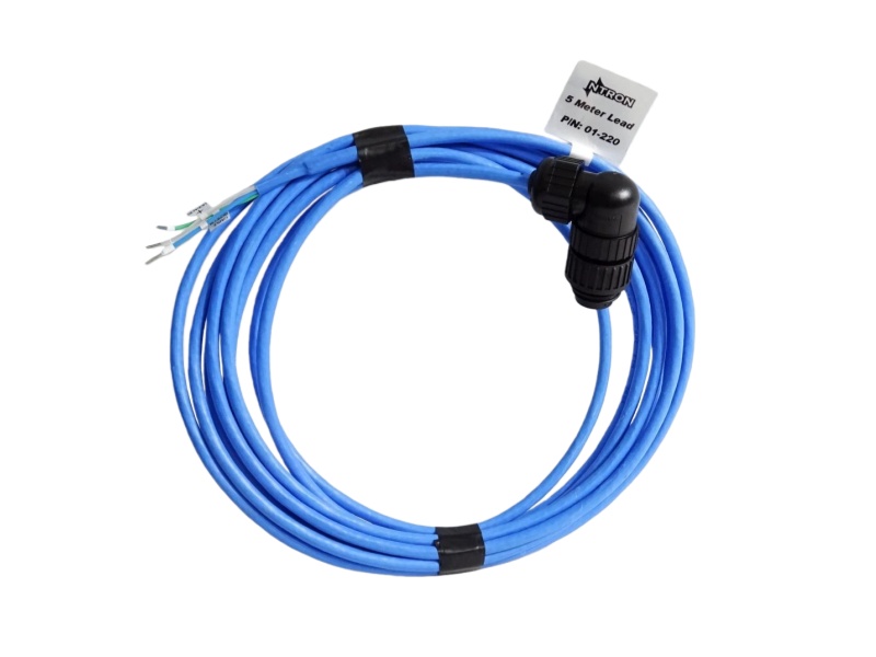
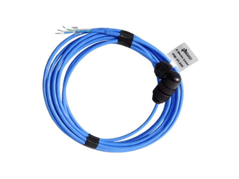
The 1770-CD Diode Cable Allen Bradley is specifically designated as a Twinaxial Cable, a critical physical medium for industrial networks like Data Highway. This specialized cable, equivalent to Belden 9463, is engineered to form the reliable backbone of a control system's communication infrastructure. Its primary role is to serve as both the main trunkline and the individual droplines, connecting various stations and controllers across the factory floor. The correct implementation of the Allen-Bradley 1794-TB3K In Stock is fundamental to establishing a robust and noise-resistant data pathway.
Proper installation of the Twinaxial Cable ALLEN BRADLEY 1770-CD is paramount for performance. The wiring recommendations specify routing it away from sources of electrical interference to minimize signal degradation. Furthermore, the cable assembly involves precise steps, including preparing the conductors by carefully removing insulation and shielding, and correctly terminating them into D-shell connectors. This meticulous process ensures the integrity of every connection point in the network.
A key feature in the use of the 1770-CD ROCKWELL Twinaxial Cable is the mandatory connection of its ground wire to an earth ground via the station connector. This grounding practice is a crucial defense mechanism, safely channeling away electrical noise and preventing it from being induced into the data lines. The shielding effectiveness of the module is a major factor in maintaining signal clarity.
In summary, the Allen-Bradley Cable 1770-CD is far more than simple wiring; it is a system-critical component. By adhering to the specified assembly and installation guidelines, the module facilitates reliable, high-integrity data exchange between programmable controllers and other devices, directly contributing to the stability and uptime of the entire industrial automation system.
If you have other request contact our team to get customized service


 Call +86 18159889985 to be connected with our Manager Stella
 Email to sales6@apterpower.com get your best quotation
 For the quick assistance message us on WhatsApp at +86 18159889985 now!
|
Allen Bradley |
1762-IF2OF2 |
Allen Bradley |
1757-FFLD2 |
Allen Bradley |
1769-BOOLEAN |
|
Allen Bradley |
1761-NET-DNI |
Allen Bradley |
1757-BEM |
Allen Bradley |
1769-CJC |
|
Allen Bradley |
1761-L32AAA |
Allen Bradley |
1763-L16BBB |
Allen Bradley |
1769-ECR |
|
Allen Bradley |
1761-CBL-HM02 |
Allen Bradley |
1764-LSP |
Allen Bradley |
1769-IM12 |
|
Allen Bradley |
1757-SRM |
Allen Bradley |
1764-MM1 |
Allen Bradley |
1769-IQ32T |
|
Allen Bradley |
1757-SRC3 |
Allen Bradley |
1766-L32BXB |
Allen Bradley |
1769-IR6 |
|
Allen Bradley |
1757-SRC1 |
Allen Bradley |
1768-EWEB |
Allen Bradley |
1769-L18ER-BB1B |
|
Allen Bradley |
1757-PLX52 |
Allen Bradley |
1769-ADN |
Allen Bradley |
1769-L18ERM-BB1B |
|
Allen Bradley |
1757-FIMRTP |
Allen Bradley |
1769-ASCII |
Allen Bradley |
1769-L20 |
|
Allen Bradley |
1757-FIM |
Allen Bradley |
1769-BA |
Allen Bradley |
1769-L30 |
Terminating Stations
This part of the procedure applies only to the first and last station connectors on the trunkline.
1. Install the 150 ohm terminator resistor by inserting it into a one inch length of shrink tubing and connecting the leads to terminals 1 and 3. The trunkline must be
terminated properly with a terminator resistor located in the station connector at each end of the trunkline.
Important: The first and last station connectors refer to the physical location along the trunkline (figure 5) and not to station addresses. Station addresses are independent of physical locations.